Tutorial: Vulkan GLSL Ray Tracing Emulator
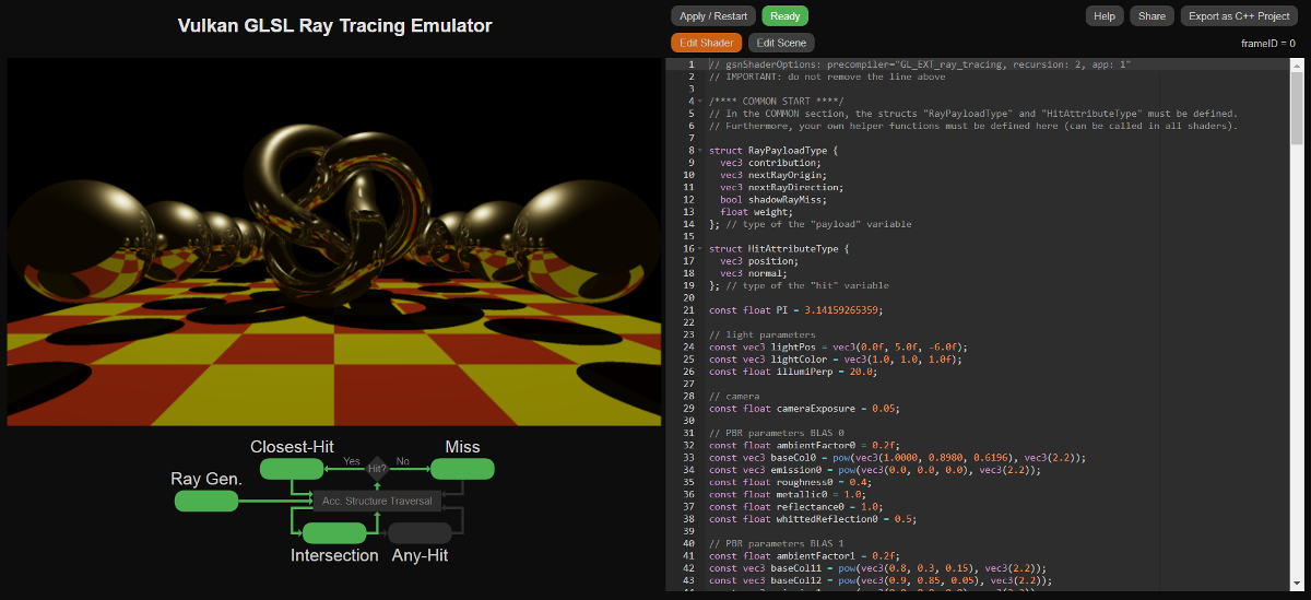
The Vulkan GLSL Ray Tracing Emulator is an online application that aims to simulate the ray tracing shader pipeline from the Vulkan GL EXT ray tracing specification.
To this end, a pre-compiler is provided that translates the ray tracing shader code into a classic WebGL GLSL fragment shader, which generates a direct preview of the shader's output image in the browser.
Most importantly, the emulator also allows exporting the ray tracing shader code as a C++ Vulkan project that can fully exploit the dedicated ray tracing acceleration hardware available in recent graphics cards (such as Nvidia Geforce RTX GPUs or the AMD RX 6000 series).
The web-based emulator is intended for computer graphics education or rapid prototyping of GLSL ray tracing shaders. It does not require a high-end GPU with special ray tracing hardware. Only if you want to run the exported C++ Vulkan stand-alone application, a GPU with ray tracing accelerator hardware is necessary.
To keep the interface as simple and accessible as possible, the online emulator provides only a limited choice of pre-defined 3D meshes and textures. However, the ray tracing shader code from the emulator can be exported as a Vulkan C++ project or as a node graph for the GSN Composer. Both export options allow changing the loaded 3D meshes and textures.
Because this tutorial complies with the standardized GLSL ray tracing specification, it is not specific to the online ray tracing emulator. Hopefully, it provides a simple entry point to the Vulkan GLSL ray tracing pipeline in general.
The Standardized Ray Tracing Pipeline
The ray tracing pipeline consists of 5 different shaders:
- Ray Generation
- Closest-Hit
- Miss
- Intersection
- Any-Hit
Roughly speaking, the pipeline works as follows.
The ray generation shader creates rays and submits them to the "acceleration structure traversal" block (see figure above)
by calling the function traceRayEXT(...).
The ray traversal block is the non-programmable part of the pipeline.
The most important parameter of the traceRayEXT function is the payload variable that
contains the collected information of the ray. The payload variable
is of user-defined type and can be modified in the shaders stages that are called for a particular ray during its traversal.
Once the ray traversal is complete, the traceRayEXT function returns to the caller and the
payload can be evaluated in the ray generation shader to produce an output image.
If the ray traversal detects an intersection of the ray with a user-defined bounding box (or triangle of a triangle mesh),
the intersection shader is called. If the intersection shader
determines that a ray-primitive intersection
has occurred within the bounding box, it notifies the ray traversal with the function reportIntersectionEXT(...).
Furthermore, the intersection shader
can fill a hitAttributeEXT variable (which can be of user-defined type). In the case of triangles,
an intersection shader is already built-in.
The built-in triangle intersection provides barycentric coordinates of the hit location
within the triangle with the "hitAttributeEXT vec2 baryCoord" variable.
For geometric primitives that are not triangles (such as cubes, cylinders, spheres, parametric surfaces, etc.) you have to
provide your custom intersection shader.
If an intersection is reported and an any-hit shader is provided, the any-hit shader
is called.
The task of the any-hit shader is to accept or ignore a hit.
A typical application for an any-hit shader is to handle a partly transparent surface.
If the hit occurs in a transparent region, it should be ignored.
A hit is ignored with the ignoreIntersectionEXT statement. It is also possible
to terminate the ray traversal in the any-hit shader with the
terminateRayEXT statement.
If no any-hit shader is provided or the ignoreIntersectionEXT statement
is not called in the shader, the hit is reported to the ray traversal.
Once the ray traversal has determined all possibles hits along the ray and at least one hit has occurred, the closest-hit shader is called for the closest one of these hits. Otherwise, if no hit occurred, the miss shader is called (see figure above). Both types of shaders can manipulate the ray payload. For example, the miss shader could submit the color of the environment into the payload and the closest-hit shader could compute the shading color for the hit surface. To this end, the closest-hit shader can access several built-in variables, such as the gl_PrimitiveID or the gl_InstanceID that are set accordingly for each hit. A full list of built-in variables is provided below.
The closest-hit and miss shader can also
call the traceRayEXT function, which submits another ray into the
ray traversal block and might create a recursion (see figure above). A typical application in the closest-hit shader
is shooting a "shadow" ray in the direction of
the light source to determine if the light is occluded by other objects.
As this ray might trigger another call of the closest-hit shader, a recursion
is created. In general, it it is recommended to keep the number of recursive function calls as low as possible for best performance.
The emulator will internally unroll these recursions because a classic WebGL GLSL fragment shader does not
support recursive function calls.
Built-In Variables
| Ray generation | Closest-hit | Miss | Intersection | Any-hit | |
uvec3 gl_LaunchIDEXT |
✓ | ✓ | ✓ | ✓ | ✓ |
uvec3 gl_LaunchSizeEXT |
✓ | ✓ | ✓ | ✓ | ✓ |
int gl_PrimitiveID |
✓ | ✓ | ✓ | ||
int gl_InstanceID |
✓ | ✓ | ✓ | ||
int gl_InstanceCustomIndexEXT |
✓ | ✓ | ✓ | ||
int gl_GeometryIndexEXT |
✓ | ✓ | ✓ | ||
vec3 gl_WorldRayOriginEXT |
✓ | ✓ | ✓ | ✓ | |
vec3 gl_WorldRayDirectionEXT |
✓ | ✓ | ✓ | ✓ | |
vec3 gl_ObjectRayOriginEXT |
✓ | ✓ | ✓ | ||
vec3 gl_ObjectRayDirectionEXT |
✓ | ✓ | ✓ | ||
float gl_RayTminEXT |
✓ | ✓ | ✓ | ✓ | |
float gl_RayTmaxEXT |
✓ | ✓ | ✓ | ✓ | |
uint gl_IncomingRayFlagsEXT |
✓ | ✓ | ✓ | ✓ | |
float gl_HitTEXT |
✓ | ✓ | |||
uint gl_HitKindEXT |
✓ | ✓ | |||
mat4x3 gl_ObjectToWorldEXT |
✓ | ✓ | ✓ | ||
mat4x3 gl_WorldToObjectEXT |
✓ | ✓ | ✓ |
Built-In Constants
const uint gl_RayFlagsNoneEXT = 0u; |
const uint gl_RayFlagsNoOpaqueEXT = 2u; |
const uint gl_RayFlagsTerminateOnFirstHitEXT = 4u; |
const uint gl_RayFlagsSkipClosestHitShaderEXT = 8u; |
const uint gl_RayFlagsCullBackFacingTrianglesEXT = 16u; |
const uint gl_RayFlagsCullFrontFacingTrianglesEXT = 32u; |
const uint gl_RayFlagsCullOpaqueEXT = 64u; |
const uint gl_RayFlagsCullNoOpaqueEXT = 128u; |
const uint gl_HitKindFrontFacingTriangleEXT = 0xFEu; |
const uint gl_HitKindBackFacingTriangleEXT = 0xFFu; |
TLAS and BLAS
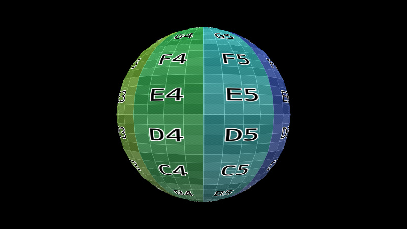
The 3D scene is represented by the acceleration structure that is used in the acceleration structure traversal block. As shown in the image below, the acceleration structure consists of a top-level acceleration structure (TLAS) and multiple bottom-level acceleration structures (BLAS). Each BLAS can be either a triangle mesh or a user-defined collection of axis-aligned bounding boxes (AABBs).
A BLAS can be instantiated in the TLAS and gets a unique gl_InstanceID.
Furthermore, each triangle in a triangle mesh and each AABB in the collection of intersection boxes gets a consecutive gl_PrimitiveID.
Each BLAS has its transformation from object to world space, which is initially assigned when the BLAS is added to the TLAS.
This transformation is accessible in the shader via the gl_ObjectToWorldEXT and
gl_WorldToObjectEXT variables.
When a hit occurs in the ray traversal and the intersection, any-hit, or closest-hit shader is called, these mentioned variables are set accordingly.
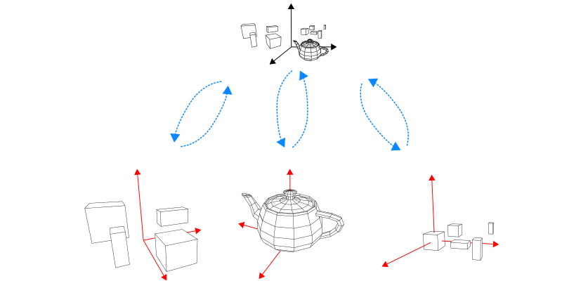
gl_ObjectToWorldEXTgl_WorldToObjectEXTgl_InstanceID = 0gl_InstanceID = 1gl_InstanceID = 2Example 1: Ray Tracing "Hello, World!"
This first minimal example consists only of a ray generation shader that is called for each pixel of the image and writes a color value into that pixel.
In the Vulkan GLSL Ray Tracing Emulator this is achieved with the following code:
// gsnShaderOptions: precompiler="GL_EXT_ray_tracing, recursion: 2, app: 1"
// IMPORTANT: do not remove the line above

/**** ABOUT ****/
// A minimal example

/**** COMMON START ****/
// In the COMMON section, the structs "RayPayloadType" and "HitAttributeType" must be defined.
// Furthermore, your own helper functions must be defined here (can be called in all shaders).

struct RayPayloadType {
  vec3 color; // unused
}; // type of the "payload" variable

struct HitAttributeType {
  vec3 normal; // unused
}; // type of the "hit" variable

/**** COMMON END ****/

// Ray tracing shaders must be defined in the following order:
// ray generation, closest-hit, miss, intersection, any-hit

void main() { /**** RAY GENERATION SHADER ****/
  // set RGBA color
  gsnSetPixel(vec4(1.0, 1.0, 0.0, 1.0));
}
All commented lines are not necessary, except for the first line, which invokes the pre-compiler. Consequently, if you like it as short as possible, this code works as well:
// gsnShaderOptions: precompiler="GL_EXT_ray_tracing, recursion: 2, app: 1"
struct RayPayloadType {
  vec3 color;
};

struct HitAttributeType {
  vec3 normal;
};

void main() {
  gsnSetPixel(vec4(1.0, 1.0, 0.0, 1.0));
}

Example 2: gl_LaunchID
Only two built-in variables are accessible in the ray generation shader, namely
uvec3 gl_LaunchIDEXT
and uvec3 gl_LaunchSizeEXT.
In the emulator, the x- and y-dimension of the gl_LaunchSizeEXT variable correspond
to the width and height of the output image and the z-dimension is always set to 1. The
gl_LaunchSizeEXT variable can be changed in the Edit Scene section of the user interface.
The ray generation shader's main() function is called (in parallel) for each pixel of the output image and
the gl_LaunchIDEXT variable can be used to determine the position within the image.
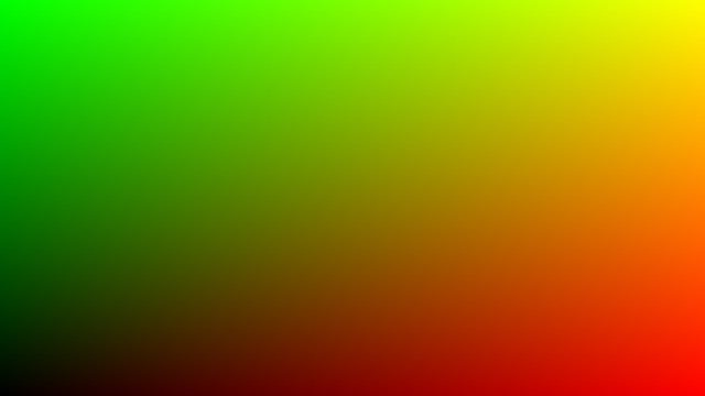
In the following example, the red and green channels of the output image are set dependent on the values in the
gl_LaunchIDEXT variable.
void main() { /**** RAY GENERATION SHADER ****/
  vec4 outputColor = vec4(0.0, 0.0, 0.0, 1.0);
  outputColor.r = float(gl_LaunchIDEXT.x) / float(gl_LaunchSizeEXT.x);
  outputColor.g = float(gl_LaunchIDEXT.y) / float(gl_LaunchSizeEXT.y);
  gsnSetPixel(outputColor);
}
Example 3: Using the Previous Image
In ray tracing, it is often required to continuously improve a rendering result over time. To this end, the emulator allows rendering multiple consecutive image frames and the shader of the current frame gets access to the previously rendered frame.
The total number of rendered image frames can be changed in the Edit Scene section of the user interface.
In the shader, the total number of frames is known via the uniform integer variable frameSize. The current frame number (starting
from 0) is given by the uniform integer variable frameID.
In this example, the first image (with frameID = 0) is set to black. Each new frame reads the pixel value
from the previous output image and adds a small color offset, such that over time, the image fades to white.
void main() { /**** RAY GENERATION SHADER ****/
  if(frameID == 0) {
     // initialize with black
     gsnSetPixel(vec4(0.0, 0.0, 0.0, 1.0));
  } else {
     vec4 previousPixel = gsnGetPreviousPixel();
     previousPixel.rgb += 1.0 / float(frameSize - 1);
     gsnSetPixel(previousPixel);
  }
}

Example 4: Camera Rays
The typical task of a ray generation shader is to shoot camera rays into the scene. In this example, it is shown how
to generate such rays for a camera that is located at the origin of the global world coordinate system and is looking in
the negative z-direction. To reuse this camera representation in later examples, the custom function getCameraRay(...)
is defined. This function is placed in the COMMON section of the shader code (above the main() function of the ray generation shader).
Functions defined in the COMMON section can be accessed by all shaders.
// gsnShaderOptions: precompiler="GL_EXT_ray_tracing, recursion: 2, app: 1"
// IMPORTANT: do not remove the line above

/**** ABOUT ****/
// Example on how to generate camera rays

/**** COMMON START ****/
// In the COMMON section, the structs "RayPayloadType" and "HitAttributeType" must be defined.
// Furthermore, your own helper functions must be defined here (can be called in all shaders).

struct RayPayloadType {
  vec3 color; // unused
}; // type of the "payload" variable

struct HitAttributeType {
  vec3 normal; // unused
}; // type of the "hit" variable

// Returns a camera ray for a camera at the origin that is looking in negative z-direction.
// "fieldOfViewY" must be given in degrees.
// "point" must be in range [0.0, 1.0] to cover the complete image plane.
//
vec3 getCameraRay(float fieldOfViewY, float aspectRatio, vec2 point) {
  // compute focal length from given field-of-view
  float focalLength = 1.0 / tan(0.5 * fieldOfViewY * 3.14159265359 / 180.0);
  // compute position in the camera's image plane in range [-1.0, 1.0]
  vec2 pos = 2.0 * (point - 0.5);
  return normalize(vec3(pos.x * aspectRatio, pos.y, -focalLength));
}

/**** COMMON END ****/

// Ray tracing shaders must be defined in the following order:
// ray generation, closest-hit, miss, intersection, any-hit

void main() { /**** RAY GENERATION SHADER ****/

  // compute the texture coordinate for the output image in range [0.0, 1.0]
  vec2 texCoord = (vec2(gl_LaunchIDEXT.xy) + 0.5) / vec2(gl_LaunchSizeEXT.xy);

  // camera's aspect ratio
  float aspect = float(gl_LaunchSizeEXT.x) / float(gl_LaunchSizeEXT.y);

  vec3 rayOrigin = vec3(0.0, 0.0, 0.0);
  vec3 rayDirection = getCameraRay(45.0, aspect, texCoord);

  gsnSetPixel(vec4(rayDirection, 1.0));
}
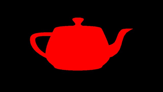
Example 5: Rendering a Triangle Mesh
We now add a closest-hit and a miss shader to render our first triangle mesh.
The camera rays from the previous example are now submitted to the "acceleration structure traversal" by calling
the built-in traceRayEXT(...) function in the ray generation shader.
If a camera ray hits the triangle mesh, the closest-hit shader is called and the payload.color variable is set to red.
Otherwise, if no hits occur, the miss shader is called and the payload.color variable is set to black.
After triggering the execution of the closest-hit or the miss shader the traceRayEXT function
returns to the calling ray generation shader and the modified payload.color variable
is written to the output image.
struct RayPayloadType {
  vec3 color;
}; // type of the "payload" variable

...

void main() { /**** RAY GENERATION SHADER ****/

  // compute the texture coordinate for the output image in range [0.0, 1.0]
  vec2 texCoord = (vec2(gl_LaunchIDEXT.xy) + 0.5) / vec2(gl_LaunchSizeEXT.xy);

  // camera's aspect ratio
  float aspect = float(gl_LaunchSizeEXT.x) / float(gl_LaunchSizeEXT.y);

  vec3 rayOrigin = vec3(0.0, 0.0, 0.0);
  vec3 rayDirection = getCameraRay(30.0, aspect, texCoord);

  uint rayFlags = gl_RayFlagsNoneEXT; // no ray flags
  float rayMin = 0.001; // minimal distance for a ray hit
  float rayMax = 10000.0; // maximum distance for a ray hit
  uint cullMask = 0xFFu; // no culling

  // Submitting the camera ray to the acceleration structure traversal.
  // The last parameter is the index of the "payload" variable (always 0)
  traceRayEXT(topLevelAS, rayFlags, cullMask, 0u, 0u, 0u, rayOrigin, rayMin, rayDirection, rayMax, 0);

  // result is in the "payload" variable
  gsnSetPixel(vec4(payload.color, 1.0));
}

void  main() { /**** CLOSEST-HIT SHADER ****/
   // set color to red
   payload.color = vec3(1.0, 0.0, 0.0);
}

void main() { /**** MISS SHADER ****/
  // set color to black
  payload.color = vec3(0.0, 0.0, 0.0);
}
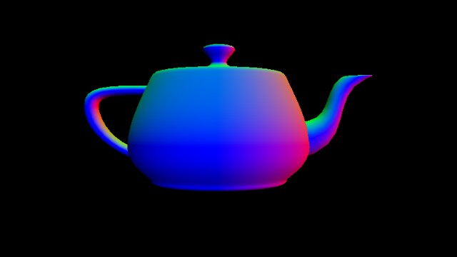
Example 6: Accessing the Vertex Data of a Triangle Mesh
When the closest-hit shader is called, the built-in variables gl_InstanceID,
gl_ObjectToWorldEXT, and gl_PrimitiveID
are set accordingly and allow to identify the BLAS instance, its transformation, and the primitive (i.e., in this case, the triangle) of the closest hit location.
The emulator provides three functions that take the gl_InstanceID and gl_PrimitiveID
variables as input parameters and return the local vertex positions, local normals, and texture coordinates for
the three vertices of the triangle that was hit.
Furthermore, the barycentric coordinates of the closest hit location are computed by
the built-in triangle intersection and are passed to the closest-hit shader via the
vec2 baryCoord variable.
Using the barycentric coordinates, the
interpolated vertex data for the hit location can be computed.
...

void  main() { /**** CLOSEST-HIT SHADER ****/

  // get mesh vertex data in object space
  vec3 p0, p1, p2;
  gsnGetPositions(gl_InstanceID, gl_PrimitiveID, p0, p1, p2);
  vec3 n0, n1, n2;
  gsnGetNormals(gl_InstanceID, gl_PrimitiveID, n0, n1, n2);
  vec2 t0, t1, t2;
  gsnGetTexCoords(gl_InstanceID, gl_PrimitiveID, t0, t1, t2);

  // interpolate with barycentric coordinates
  vec3 barys = vec3(1.0f - baryCoord.x - baryCoord.y, baryCoord.x, baryCoord.y);
  vec3 localNormal = normalize(n0 * barys.x + n1 * barys.y + n2 * barys.z);
  vec3 localPosition = p0 * barys.x + p1 * barys.y + p2 * barys.z;
  vec2 texCoords = t0 * barys.x + t1 * barys.y + t2 * barys.z;

  // transform to world space
  mat3 normalMat;
  gsnGetNormal3x3Matrix(gl_InstanceID, normalMat);
  vec3 normal = normalize(normalMat * localNormal);
  vec3 position = gl_ObjectToWorldEXT * vec4(localPosition, 1.0);

  payload.color = normal;
}
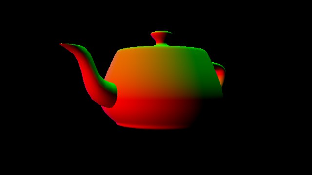
Example 7: Moving the Camera
In this example, a new helper function is added to the COMMON section that produces rays for a camera that is looking from an "eye" point to reference point (both in world space). Changing the camera parameters over time generates a moving camera.
// Returns a camera ray for a camera located at the
// eye point and looking at a reference point. Furthermore,
// the up vector of the camera coordinate system is required.
// (similar to the OpenGL gluLookAt function)
// "fieldOfViewY" must be given in degrees.
// "point" must be in range [0.0, 1.0] to cover the complete image plane.
//
vec3 getCameraRayLookAt(float fieldOfViewY, float aspectRatio,
                        vec3 eye, vec3 ref, vec3 up, vec2 point)
{
  // compute focal length from given field-of-view
  float focalLength = 1.0 / tan(0.5 * fieldOfViewY * 3.14159265359 / 180.0);
  // compute position in the camera's image plane in range [-1.0, 1.0]
  vec2 pos = 2.0 * (point - 0.5);
  // compute ray in camera space
  vec3 rayCam = vec3(pos.x * aspectRatio, pos.y, -focalLength);

  // compute camera axes in world space
  vec3 camZ = normalize(eye - ref);
  vec3 v = normalize(up);
  vec3 camX = cross(v, camZ);
  vec3 camY = cross(camZ, camX);

  vec3 rayWorld = camX * rayCam.x + camY * rayCam.y + camZ * rayCam.z;
  return normalize(rayWorld);
}
Example 8: Textures
Textures can be accessed in the same way as known from rasterization shaders:
texture(sampler2D sampler, vec2 p);.
Or you can manually select the level-of-detail for the mipmap with the textureLod function and its lod parameter:
textureLod(sampler2D sampler, vec2 p, float lod);
If you want to access individual pixels directly with integer indices, you can also use
texelFetch(sampler2D sampler, ivec2 p, int lod);
The size of the texture can be determined by
textureSize(sampler2D sampler, int lod);
In the emulator, five sampler2D variables are predefined. They are
called texture0, texture1 ... texture4. The assigned images can be selected in the
Edit Scene section of the user interface.
...
void  main() { /**** CLOSEST-HIT SHADER ****/
  ...
  payload.color = textureLod(texture0, texCoords, 0.0).rgb;
}
Example 9: Shooting a Shadow Ray
The closest-hit and the miss shader can also call the traceRayEXT function to submit a ray into the
acceleration structure traversal. In this example,
the closest-hit shader calls traceRayEXT to send a shadow ray in the direction of the light source.
Notice, that the arrow from the output of the closest-hit shader turns green in the shader schematic of the emulator (also shown in the schematic here):
The shadow ray's task is to inform the emitting closest-hit shader whether or not there are any object between the hit point and the light source.
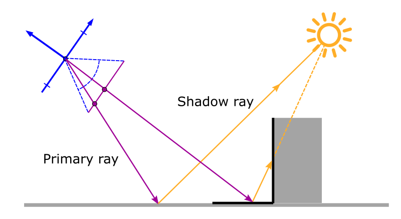
If a hit occurs on the ray path towards the light, we are not interested in calling the closest-hit shader for that hit. Therefore, we
can set the ray flags to gl_RayFlagsSkipClosestHitShaderEXT. Furthermore, we can save computation in the ray traversal because we do not need to find the closest hit. The ray traversal can
already terminate on the first hit, which is why we additionally set the gl_RayFlagsTerminateOnFirstHitEXT flag.
If no hit occurs for the shadow ray, the miss shader is called and it sets the payload.shadowRayMiss variable from false to true.
When the traceRayEXT function returns to the emitting closest-hit shader,
this variable can be checked to determine if the surface point is in shadow or not.
struct RayPayloadType {
  vec3 color;
  bool shadowRayMiss;
}; // type of the "payload" variable

...

void  main() { /**** CLOSEST-HIT SHADER ****/

  // get mesh vertex data in object space
  vec3 p0, p1, p2;
  gsnGetPositions(gl_InstanceID, gl_PrimitiveID, p0, p1, p2);
  vec3 n0, n1, n2;
  gsnGetNormals(gl_InstanceID, gl_PrimitiveID, n0, n1, n2);
  vec2 t0, t1, t2;
  gsnGetTexCoords(gl_InstanceID, gl_PrimitiveID, t0, t1, t2);

  // interpolate with barycentric coordinate
  vec3 barys = vec3(1.0f - baryCoord.x - baryCoord.y, baryCoord.x, baryCoord.y);
  vec3 localNormal = normalize(n0 * barys.x + n1 * barys.y + n2 * barys.z);
  vec3 localPosition = p0 * barys.x + p1 * barys.y + p2 * barys.z;
  vec2 texCoords = t0 * barys.x + t1 * barys.y + t2 * barys.z;

  // transform to world space
  mat3 normalMat;
  gsnGetNormal3x3Matrix(gl_InstanceID, normalMat);
  vec3 normal = normalize(normalMat * localNormal);
  vec3 position = gl_ObjectToWorldEXT * vec4(localPosition, 1.0);

  // dynamic light location
  float t = float(frameID % 45)/float(45);
  vec3 lightPos = vec3(5.0 * sin(2.0*PI*t), 5.0 * cos(2.0*PI*t),  5.0);
  vec3 lightDir = normalize(lightPos - position);

  // prepare shadow ray
  uint rayFlags = gl_RayFlagsTerminateOnFirstHitEXT | gl_RayFlagsSkipClosestHitShaderEXT;
  float rayMin     = 0.001;
  float rayMax     = length(lightPos - position);
  float shadowBias = 0.001;
  uint cullMask = 0xFFu;
  float frontFacing = dot(-gl_WorldRayDirectionEXT, normal);
  vec3 shadowRayOrigin = position + sign(frontFacing) * shadowBias * normal;
  vec3 shadowRayDirection = lightDir;
  payload.shadowRayMiss = false;

  // shot shadow ray
  traceRayEXT(topLevelAS, rayFlags, cullMask, 0u, 0u, 0u,
         shadowRayOrigin, rayMin, shadowRayDirection, rayMax, 0);

  // diffuse shading
  vec3 radiance = ambientColor; // ambient term
  if(payload.shadowRayMiss) { // if not in shadow
    float irradiance = max(dot(lightDir, normal), 0.0);
    if(irradiance > 0.0) { // if receives light
      radiance += baseColor * irradiance; // diffuse shading
    }
  }

  payload.color = vec3(radiance);
}

void main() { /**** MISS SHADER ****/
  // set color to black
  payload.color = vec3(0.0, 0.0, 0.0);
  // shadow ray has not hit an object
  payload.shadowRayMiss = true;
}

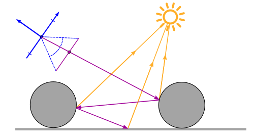
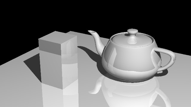
Example 10: Reflections / Avoiding Recursion
For ray hits on a reflective surface, the reflected ray can be calculated and traced into the scene. In a first simple model, we assume that the radiance at a surface point is the sum of the direct light from the light source plus the radiance contribution from the reflected ray. The reflected ray might be reflected again at the next hit. The ray tracer only stops at non-reflective surfaces. Therefore, the number of reflections must be limited, otherwise, there might be an endless loop.
Reflections can be implemented very easily with recursive function calls:
trace(level, ray, &color) { // THIS IS PSEUDOCODE!!!
  if (intersect(ray, &hit)) {
    shadow = testShadow(hit);
    directColor = getDirectLight(hit, shadow);
    if (reflectionFactor > 0.0 && level < maxLevel) {
      reflectedRay = reflect(ray, hit.normal);
      trace(level + 1, reflectedRay, &reflectionColor); // recursion
    }
    color = color + directColor + reflectionFactor * reflectionColor;
  } else {
    color = backgroundColor;
  }
}
However, when working with ray tracing shaders, the number of recursive function calls should be kept as low as possible. Fortunately, the same result can also be achieved without recursion:
trace(ray, &color) { // THIS IS PSEUDOCODE!!!
  nextRay = ray;
  contribution = 1.0;
  level = 0;
  while (nextRay && level < maxLevel) {
    if (intersect(nextRay, &hit)) {
      shadow = testShadow(hit);
      directColor = getDirectLight(hit, shadow);
      if (reflectionFactor > 0.0) {
        reflectedRay = reflect(nextRay, hit.normal);
        nextRay = reflectedRay;
      } else {
        nextRay = false;
      }
    } else {
      directColor = backgroundColor;
      nextRay = false;
    }
    color = color + contribution * directColor;
    contribution = contribution * reflectionFactor;
    level = level + 1;
  }
}
Using iteration instead of recursion leads to the following ray tracing shader code:
struct RayPayloadType {
  vec3 directLight;
  vec3 nextRayOrigin;
  vec3 nextRayDirection;
  float nextReflectionFactor;
  bool shadowRayMiss;
}; // type of the "payload" variable

...

void main() { /**** RAY GENERATION SHADER ****/

  // compute the texture coordinate for the output image in range [0.0, 1.0]
  vec2 texCoord = (vec2(gl_LaunchIDEXT.xy) + 0.5) / vec2(gl_LaunchSizeEXT.xy);

  // camera parameter
  float aspect = float(gl_LaunchSizeEXT.x) / float(gl_LaunchSizeEXT.y);
  vec3 rayOrigin = camPos;
  vec3 rayDirection = getCameraRayLookAt(20.0, aspect, camPos, camLookAt, camUp, texCoord);

  uint rayFlags = gl_RayFlagsNoneEXT; // no ray flags
  float rayMin = 0.001; // minimum ray distance for a hit
  float rayMax = 10000.0; // maximum ray distance for a hit
  uint cullMask = 0xFFu; // no culling

  // init ray and payload
  payload.nextRayOrigin = rayOrigin;
  payload.nextRayDirection = rayDirection;
  payload.nextReflectionFactor = 1.0;
  float contribution = 1.0;
  vec3 color = vec3(0.0, 0.0, 0.0);
  int level = 0;
  const int maxLevel = 5;

  // shot rays
  while(length(payload.nextRayDirection) > 0.1 &&
        level < maxLevel && contribution > 0.001) {
    // Submitting the camera ray to the acceleration structure traversal.
    // The last parameter is the index of the "payload" variable (always 0)
    traceRayEXT(topLevelAS, rayFlags, cullMask, 0u, 0u, 0u,
            payload.nextRayOrigin, rayMin, payload.nextRayDirection, rayMax, 0);
    color += contribution * payload.directLight;
    contribution *= payload.nextReflectionFactor;
    level++;
  }

  gsnSetPixel(vec4(color, 1.0));
}

void  main() { /**** CLOSEST-HIT SHADER ****/

  // get mesh vertex data in object space
  vec3 p0, p1, p2;
  gsnGetPositions(gl_InstanceID, gl_PrimitiveID, p0, p1, p2);
  vec3 n0, n1, n2;
  gsnGetNormals(gl_InstanceID, gl_PrimitiveID, n0, n1, n2);
  vec2 t0, t1, t2;
  gsnGetTexCoords(gl_InstanceID, gl_PrimitiveID, t0, t1, t2);

  // interpolate with barycentric coordinate
  vec3 barys = vec3(1.0f - baryCoord.x - baryCoord.y, baryCoord.x, baryCoord.y);
  vec3 localNormal = normalize(n0 * barys.x + n1 * barys.y + n2 * barys.z);
  vec3 localPosition = p0 * barys.x + p1 * barys.y + p2 * barys.z;
  vec2 texCoords = t0 * barys.x + t1 * barys.y + t2 * barys.z;

  // transform to world space
  mat3 normalMat;
  gsnGetNormal3x3Matrix(gl_InstanceID, normalMat);
  vec3 normal = normalize(normalMat * localNormal);
  vec3 position = gl_ObjectToWorldEXT * vec4(localPosition, 1.0);

  vec3 lightDir = normalize(lightPos - position);

  // prepare shadow ray
  uint rayFlags = gl_RayFlagsTerminateOnFirstHitEXT | gl_RayFlagsSkipClosestHitShaderEXT;
  float rayMin     = 0.001;
  float rayMax     = length(lightPos - position);
  float shadowBias = 0.001;
  uint cullMask = 0xFFu;
  float frontFacing = dot(-gl_WorldRayDirectionEXT, normal);
  vec3 shadowRayOrigin = position + sign(frontFacing) * shadowBias * normal;
  vec3 shadowRayDirection = lightDir;
  payload.shadowRayMiss = false;

  // shot shadow ray
  traceRayEXT(topLevelAS, rayFlags, cullMask, 0u, 0u, 0u,
         shadowRayOrigin, rayMin, shadowRayDirection, rayMax, 0);

  // diffuse shading (direct light)
  vec3 radiance = ambientColor; // ambient term
  if(payload.shadowRayMiss) { // if not in shadow
    float irradiance = max(dot(lightDir, normal), 0.0);
    if(irradiance > 0.0) { // if receives light
      radiance += baseColor * irradiance; // diffuse shading
    }
  }
  payload.directLight = radiance;

  // compute reflected ray (prepare next traceRay)
  float reflectionFactor = 0.25;
  if(reflectionFactor > 0.0) {
    payload.nextRayOrigin = position;
    payload.nextRayDirection = reflect(gl_WorldRayDirectionEXT, normal);
    payload.nextReflectionFactor = reflectionFactor;
  } else {
    // no more reflections
    payload.nextRayOrigin = vec3(0.0, 0.0, 0.0);
    payload.nextRayDirection = vec3(0.0, 0.0, 0.0);
  }
}

void main() { /**** MISS SHADER ****/
  // set color to black
  payload.directLight = vec3(0.0, 0.0, 0.0);
  // shadow ray has not hit an object
  payload.shadowRayMiss = true;
  // no more reflections
  payload.nextRayOrigin = vec3(0.0, 0.0, 0.0);
  payload.nextRayDirection = vec3(0.0, 0.0, 0.0);
}
Example 11: Distributed Ray Tracing / Anti-Aliasing
To prevent aliasing due to undersampling, we can send multiple rays per pixel. The random position of the ray inside the pixel must be uniformly distributed. To prevent repeated sampling at the same position, pseudo-random low discrepancy sequences (such as the Halton or Hammersley) are often used in practice. By averaging the contributions of the rays, the correct color value for the pixel can be determined.
If the previous average is saved in the previous image, the new average can be calculated as follows:
vec4 previousAverage = gsnGetPreviousPixel();
vec3 newAverage = (previousAverage.rgb * float(frameID) + payload.color) / float(frameID + 1);
gsnSetPixel(vec4(newAverage, 1.0));
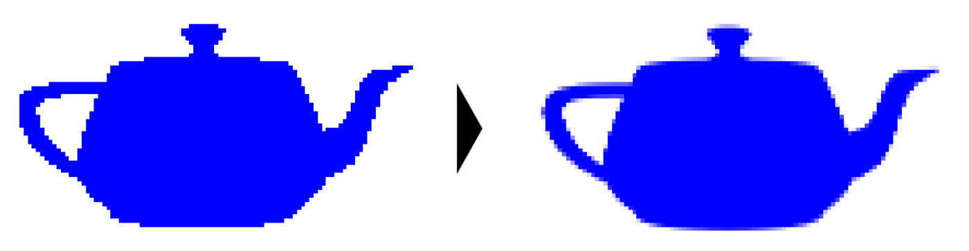
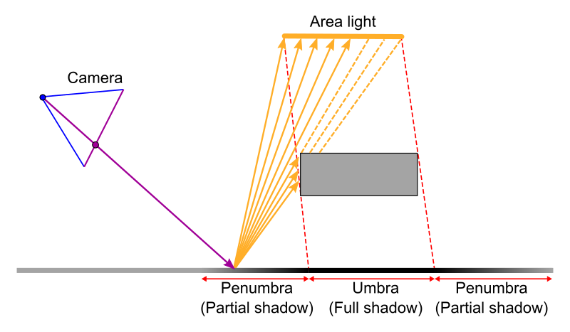
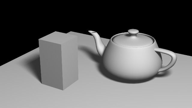
Example 12: Distributed Ray Tracing / Soft Shadows
Distributed Ray Tracing (Cook et al., Siggraph 1984) is not only suitable for anti-aliasing but it can also be used to create soft shadows. To this end, the position on an area light source is varied randomly (with a uniform distribution). Further applications of distributed ray tracing are glossy surfaces, motion blur, depth of field, etc.
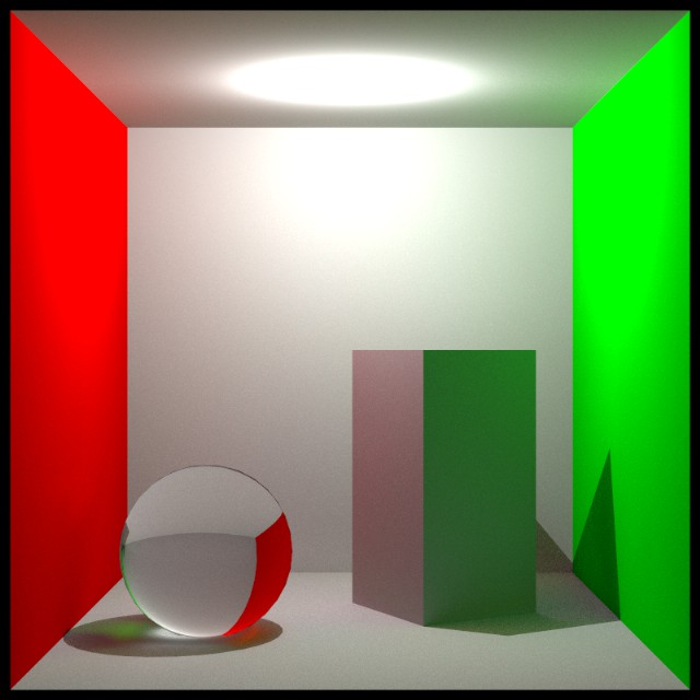
Example 13: Path Tracing
If distributed ray tracing was used for indirect light (e.g. for indirect diffuse reflection) this would quickly result in problems as the number of rays grows exponentially. The indirections of a higher degree have a smaller contribution to the image but use significantly more rays than the lower indirections.
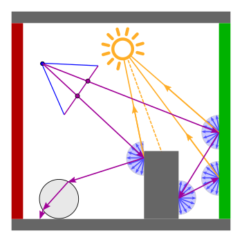
Path Tracing (Kajiya, Siggraph 1986) provides a solution to this problem by selecting only 1 ray from all possible rays at each hit. This creates 1 path per primary ray. The idea is to trace many different paths per camera pixel and calculate the mean. The advantage of this approach is that all indirections receive the same computational effort.
The path tracing example in this section uses a simple model with two different materials: An ideal refraction for the sphere on the left and a diffuse reflection everywhere else. The diffuse reflection is computed by the sum of the direct component (from the light source) and the indirect diffuse reflection (from all directions). The resulting rendering in the Cornell Box contains the famous "color bleeding" from the colored wall onto the nearby surfaces.
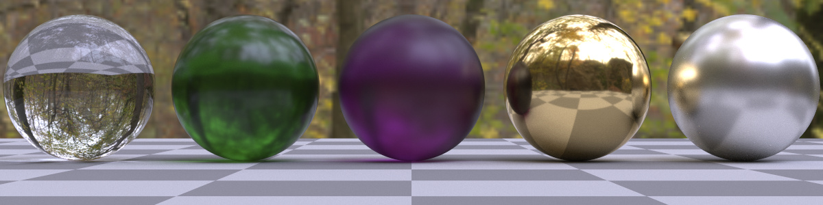
Example 14: Path Tracing with PBR Materials
This example upgrades the material model to the GGX microfacet BRDF [Walter et al. 2007, Disney 2012] that is popular in physical-based rendering (PBR).
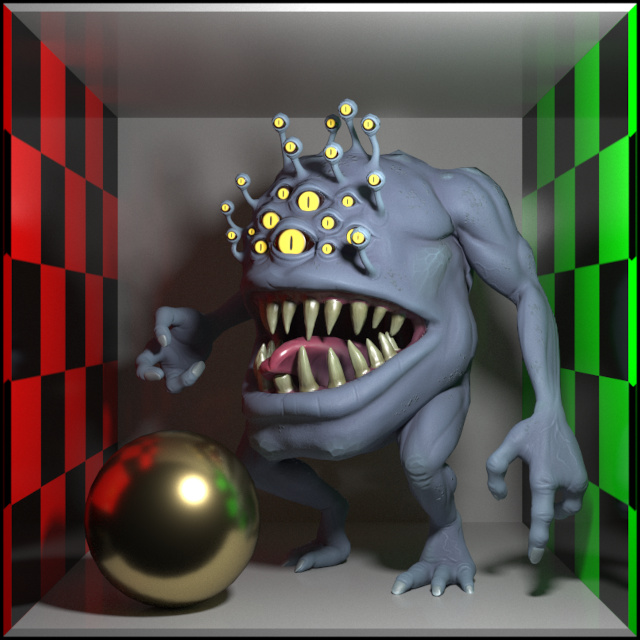
Example 15: PBR Materials with Specular Transmission
This example shows how to add specular transmission to the basic PBR material from the example above (as described in [Disney 2015]).