Rendering a 3D Scene with the GSN Composer
The GSN Composer is a free web-based visual programming environment where inputs and outputs of ready-made nodes are connected to generate an executable data-flow graph. The GSN Composer provides a number of nodes designed to be used together to render a 3D scene.
There are two rendering pipelines:
- Rasterizer for real-time rendering
- Ray Tracer for higher realism, but with significantly longer rendering times
Both rendering pipelines are specifically designed for the GSN Composer and do not use external libraries. Due to their shared 3D scene description, it is possible to freely switch between the rendering pipelines.
If you are new to the GSN Composer, you might want to start with the general Getting Started page before following the tutorial on this page.
3D.Data.Mesh
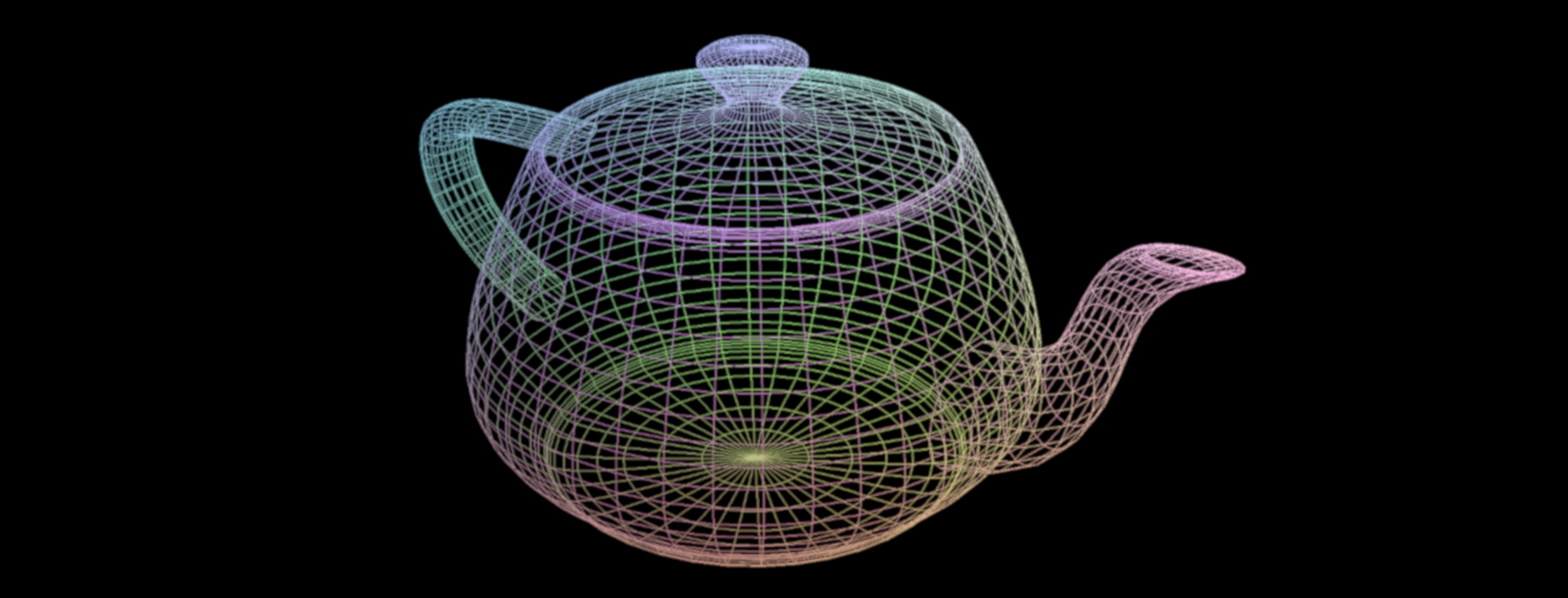
This node represents a 3D polygon mesh. A 3D mesh contains a list of vertices, which are points in 3D space. Beyond its 3D position, each vertex can store additional per-vertex attributes like its surface normal, tangent, or texture coordinate. Connecting the vertices with polygons creates the mesh's 3D surface. The GSN Composer supports two types of polygons: triangles, which are formed from three vertices, and quads (short for quadrilaterals), which have four vertices.
A mesh can be created using simple, predefined primitives (such as spheres, cubes, and cylinders) provided directly by the GSN Composer. Alternatively, a mesh can be loaded from a Wavefront OBJ file.
In the example below, a 3D.
3D.Compute.MeshGroup.GetGroup
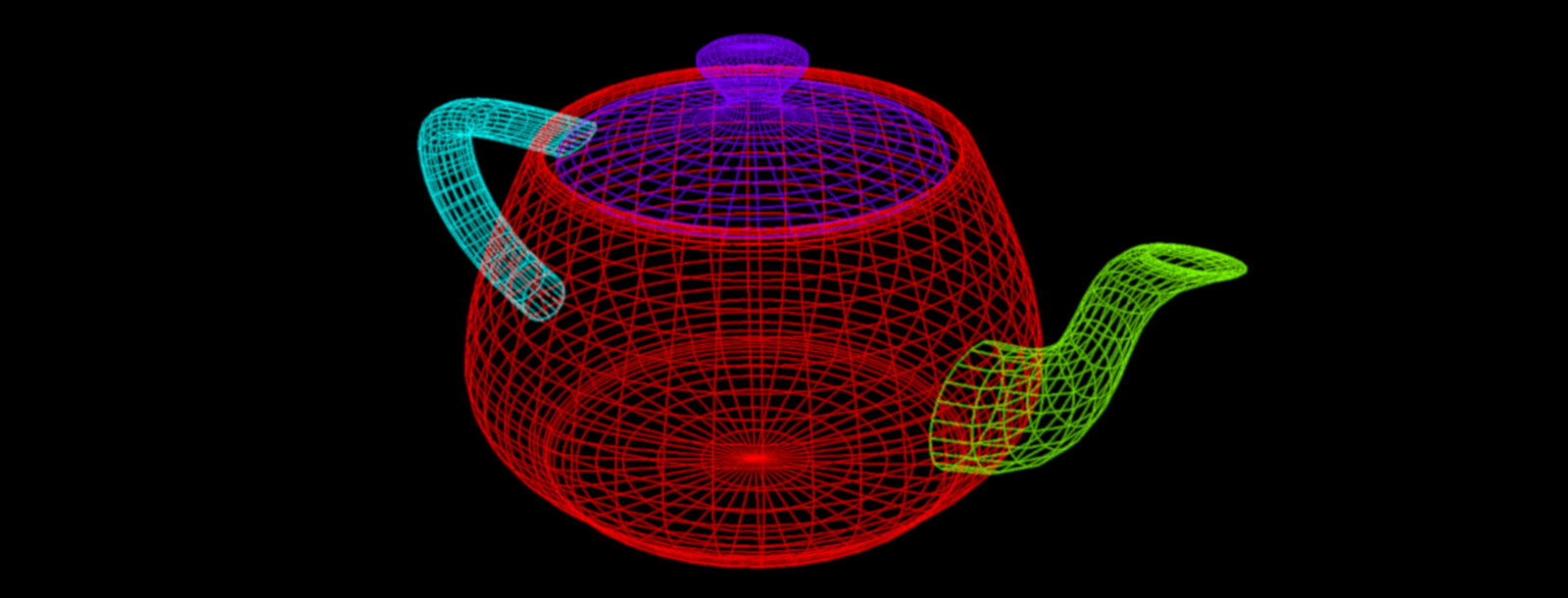
A 3D mesh might contain several mesh groups. As we will see later in this tutorial, mesh groups can be used to assign different materials to different parts of the mesh. The GetGroup node extracts a mesh group and creates a new mesh that only contains that group. The index input slot selects the mesh group with the given index.
In the example below, the previous example was extended with a GetGroup node to extract the lid of the teapot.
3D.Compute.Scene.MeshInstance
In previous examples, we were introduced to 3D polygon meshes. An instance of a 3D mesh can be added to a 3D scene using a MeshInstance node. The 3D scene representation does not store the mesh data itself, but instead keeps a reference to the input 3D mesh. This means that the same mesh can be used multiple times in the same scene by using multiple MeshInstance nodes. Reusing resources like this can save a lot of memory because the mesh data is stored only once.
Each instance of the mesh can have its own transformation. The location in the scene can be set using the positionX, positionY, and positionZ input slots of the MeshInstance node. The rotation can be defined via the rotationX, rotationY, and rotationZ input slots. The sequence of rotation is first around the z-axis, then around the y-axis, and finally around the x-axis. The scale input allows for uniform scaling, and the hide input hides the mesh instance.
Before we create and render the first scene. Let's introduce two essential helper nodes.
3D.Compute.SceneHelper.ReferenceGrid
The ReferenceGrid node adds a reference grid (with grid lines and coordinate axes) to the scene. By default, the reference grid is at the origin of the scene, and the grid plane is the x-y plane. Consequently, the positive z-axis is the default up-direction in the GSN Composer, consistent with many other 3D applications, such as Blender. However, you can toggle the grid plane to the x-z or y-z plane using the grid plane input slot.
3D.Compute.SceneHelper.SceneInspector
The SceneInspector node allows the inspection of a given 3D scene. It renders a preview of the input scene using different rendering presets, which can be selected with the render input slot.
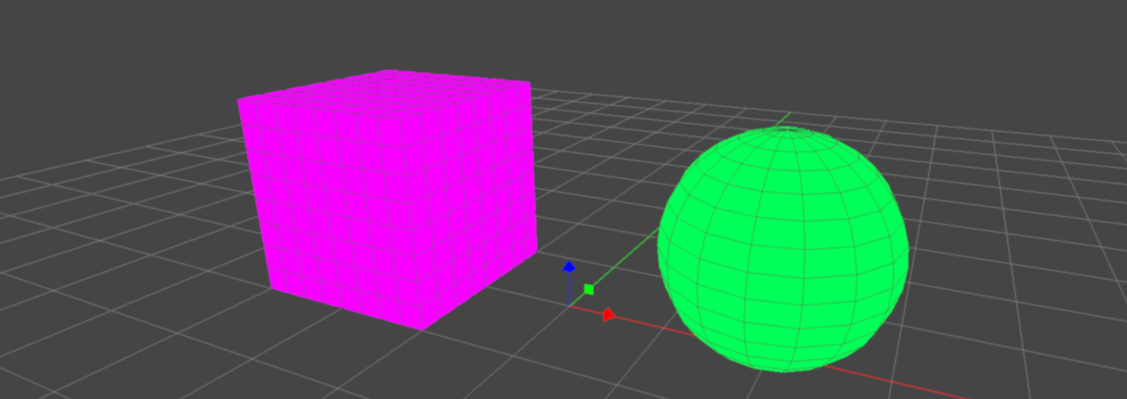
As a first example, let's create a scene with three elements: a sphere, a cube, and a reference grid.
In the example below, we use a MeshInstance node to add the sphere mesh to the scene and another one to add the cube mesh. The resulting output scenes of the two MeshInstance nodes are merged together to form a conjoined scene. Next, the reference grid is merged with the conjoined scene. The final scene now contains a total of three elements and is connected to the input of the SceneInspector node.
When you open the example below, you can experiment with the SceneInspector node by changing the scene that is connected to its InputScene slot. For example, if you connect the SceneInspector directly to the output of one of the two MeshInstance nodes, only one mesh (sphere or cube) is displayed.
The SceneInspector node has a user interface to control its own camera to view the scene. If you want to hide this interface, you can set the ModeSelect input slot to "External". Then you can select the camera motion mode externally with the mode input instead of using the user interface. If the keyboard input is enabled and the camera mode is set to "Pan-Tilt", the WASD keys can be used for camera movement. The keyboard input only works while holding down the left mouse button in the output area of the SceneInspector node:
- W (Forward): Moves the camera forward.
- A (Left): Moves the camera to the left.
- S (Backward): Moves the camera backward.
- D (Right): Moves the camera to the right.
- Q (Down): Moves the camera down.
- E (Up): Moves the camera up.
The internal camera parameters are exposed via the SceneInspector node's output slots. Furthermore, there is an OutputScene slot. The OutputScene Mode input slot selects if the internal camera of the SceneInspector node is added to the output scene as an active camera, an inactive camera, or if the output scene is an unaltered copy of the input scene. Consequently, the SceneInspector node can be used to add a camera to the scene as an alternative to the Camera node (which is described next).
3D.Compute.Scene.Camera
This node adds a perspective camera to the scene.

The camera's location in the scene can be set using the positionX, positionY, and positionZ input slots. The camera looks at a specific target location that is given by the targetX, targetY, and targetZ inputs. The "up" vector defines the direction that points upward in the 2D camera view. It can be set via the upX, upY, and upZ inputs.
The field of view input slot defines the camera's opening angle in the up-direction in degrees. A wide-angle camera has a large opening angle, and a telephoto camera has a small opening angle. The opening angle defines the view pyramid, which is truncated by the near plane and far plane to form the camera's view frustum (see figure above).
The active input sets the camera to be active. If multiple cameras are active, the first camera found while traversing the scene tree is used. The hide input hides the camera.
The camera's aspect ratio can not be set. It is automatically determined during rendering and depends on the width and height of the output image.
3D.Compute.Scene.LightDirectional
This node adds a directional light to the scene. It simulates light from a source that is so far away that all of its light rays can be considered parallel. A typical real-world application is to simulate sunlight.
The irradiance input slot defines the light's irradiance in watts per square meter under perpendicular incidence. For physically correct shading calculations, the GSN Composer assumes that one unit in world space corresponds to one meter. If you use another unit to model your scene, this has to be factored into the irradiance value that you set for your light source.

The direction of the parallel light rays is defined indirectly via a position and a target (see figure above). The ray's direction is computed from the normalized difference between the target and the position vector. The light's position can be set with the positionX, positionY, and positionZ input slots. The target location is defined by the targetX, targetY, and targetZ inputs.
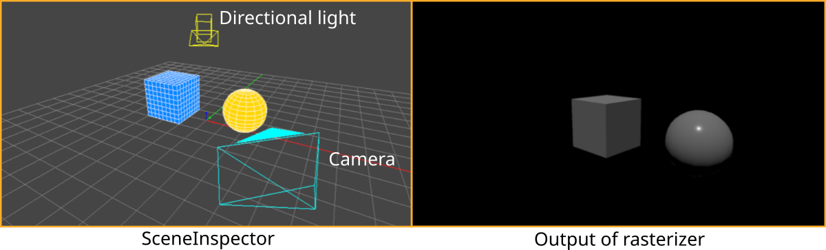
Though for rendering only the direction of the light rays is relevant and not the light's position, the position is nevertheless useful to define where the light's glyph is displayed when viewing the scene with the SceneInspector (see example below).
The color input defines the color of the light. It is given as an sRGB value and is converted to linear RGB before being applied in the shader.
Mathematically, a directional light with irradiance $E_\perp$, linear color $\mathbf{c}_{\small light}$, and light ray direction $(-\mathbf{l})$ produces at a surface with BRDF $\mathrm{f}_r(\mathbf{v}, \mathbf{l})$ and surface normal $\mathbf{n}$, the following outgoing radiance $L_o(\mathbf{v})$ in the direction $\mathbf{v}$ :
In the example below, a directional light and a camera are added to the scene from the previous example. The resulting scene is used as input for a Rasterizer node that renders the scene from the viewpoint of the added camera and produces the shown output.
3D.Compute.Render.Rasterizer
The rasterizer node renders a 3D scene using a rasterization pipeline. This is faster than ray tracing but less realistic.
An essential input of the rasterizer is the InputScene slot, which expects a scene data node. A scene data node contains a description of how the scene is composed. It consists of a hierarchical scene tree that contains parameters of scene elements (cameras, lights, etc.)
Given the scene input, the rasterizer generates a rendering of the scene using the first active camera that is found in the scene tree. If no active camera is found, a default camera is used.
The canvas width and canvas height inputs define the size of the output image.
A scene may contain multiple layers that are separately rendered on top of each other. The layer input selects the scene layer that is rendered. If the layer is set to "-1" all available layers are rendered.
The background input selects the color of the background that the canvas is filled with before any layer is rendered.
The tone mapping input selects the tone mapping approach that is applied before an outgoing radiance $L_o$ is written to the output image:
- sRGB (default): transforms the outgoing radiance $L_o$ to sRGB, which is the standard color space used for images in the GSN Composer
- Filmic: uses the Filmic tone mapping operator
- Linear: no color transformation is applied to the outgoing radiance $L_o$
- Raw: same as "linear", but all other settings clamp the output values to the range [0.0, 1.0], which is not done here
The wireframe input activates an overlay of a wireframe rendering for the meshes. The wireframe's color can be selected with the wire color input.
The glyphs input activates the rendering of glyphs for otherwise non-visible scene elements, such as lights, cameras, or helpers.
3D.Compute.Scene.MaterialBasic
The MaterialBasic node sets a basic PBR metallic-roughness material for all of its child meshes in the scene.
If another MaterialBasic node is added to the scene further down the scene tree (closer to the child mesh), it overwrites the settings of the MaterialBasic node higher up the tree.
The input parameters of the MaterialBasic node are the typical PBR metallic-roughness properties as used by many other applications and 3D formats, such as glTF. A detailed explanation of the parameters is given in the video below:
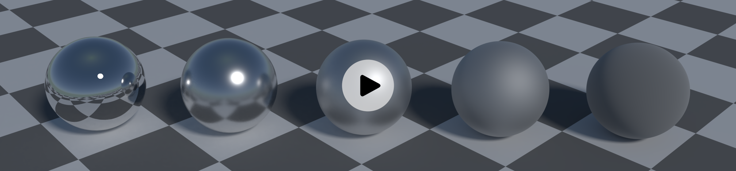
The metallic input can be set to 0.0 for a non-metallic (dielectric) surface and to 1.0 for metals.
The roughness input selects the roughness of the surface in the range [0.0, 1.0]. A value of 0.0 defines a perfectly smooth, polished surface. It will behave like a perfect mirror. A value of 1.0 defines a very rough material, with a lot of bumpiness in the microfacets.
The base color input defines the albedo for a non-metallic (dielectric) surface or the specular color for metals. It is given as an sRGB value and is converted to linear RGB before being applied in the shader.
The reflectance input defines the Fresnel reflectance for a non-metallic (dielectric) surface in the range [0.0, 1.0]. A value of 0.5 represents the Fresnel reflectance of glass. A value of 1.0 is approximately the reflectance of diamonds.
The emission input sets the emissive radiance (in watts per steradian per square meter). It is given as an sRGB value and is converted to linear RGB before being applied in the shader.
The mesh group input selects to which mesh group the material is applied ("-1" = all mesh groups). This means that a mesh with multiple mesh groups can have multiple materials assigned to it. If another MaterialBasic node with the same mesh group is added to the scene further down the scene tree (closer to the child mesh), it overwrites the settings of the MaterialBasic node with the same mesh group higher up the tree. If the mesh group is set to "-1", the materials settings for all MaterialBasic nodes higher up the tree are overwritten.
Setting the bypass input to "true" bypasses the effect of the MaterialBasic node.
Mathematically, the MaterialBasic node implements the following BRDF (Bidirectional Reflectance Distribution Function):
- Schlick Fresnel approximation: $$F(\mathbf{v}, \mathbf{h}) = \mathrm{F}_0 + \left(1.0 − \mathrm{F}_0\right) \left(1.0 − \langle\mathbf{v} \cdot \mathbf{h}\rangle \right)^5$$
-
GGX normal distribution function:
$\mathrm{D}(\mathbf{h}) = \frac{\alpha^2}{\pi \left(\langle\mathbf{n} \cdot \mathbf{h}\rangle^2 (\alpha^2-1)+1\right)^2}$ with $\alpha = r_p^2$
-
Smith-Schlick-GGX geometry term:
$\mathrm{G}_{\tiny \mbox{Smith}}(\mathbf{l}, \mathbf{v}) = \mathrm{G}_1(\mathbf{l})\, \mathrm{G}_1(\mathbf{v})$ with $\mathrm{G}_{1\ \tiny \mbox{Schlick-GGX}}(\mathbf{v}) =\frac{\langle\mathbf{n} \cdot \mathbf{v}\rangle}{\langle\mathbf{n} \cdot \mathbf{v}\rangle(1 - \frac{\alpha}{2}) + \frac{\alpha}{2} }$
- $m$ is the metallic parameter in the range [0.0, 1.0]
- $r_p$ is the roughness in the range [0.0, 1.0]
- $\mathbf{c}_{\small base}$ is the linear base color
- $f_{\small dielectric}$ is the reflectance in the range [0.0, 1.0]
- $\mathbf{n}$ is the surface normal
- $\mathbf{v}$ is the view direction
- $\mathbf{l}$ is the light direction
- $\mathbf{h}$ is the halfway vector $\mathbf{h} = \frac{\mathbf{v} + \mathbf{l}}{|\mathbf{v} + \mathbf{l}|}$
Before creating an example that uses the MaterialBasic node, we will introduce the ImageBasedLighting node, since the different material properties are most clearly visible under image-based lighting.
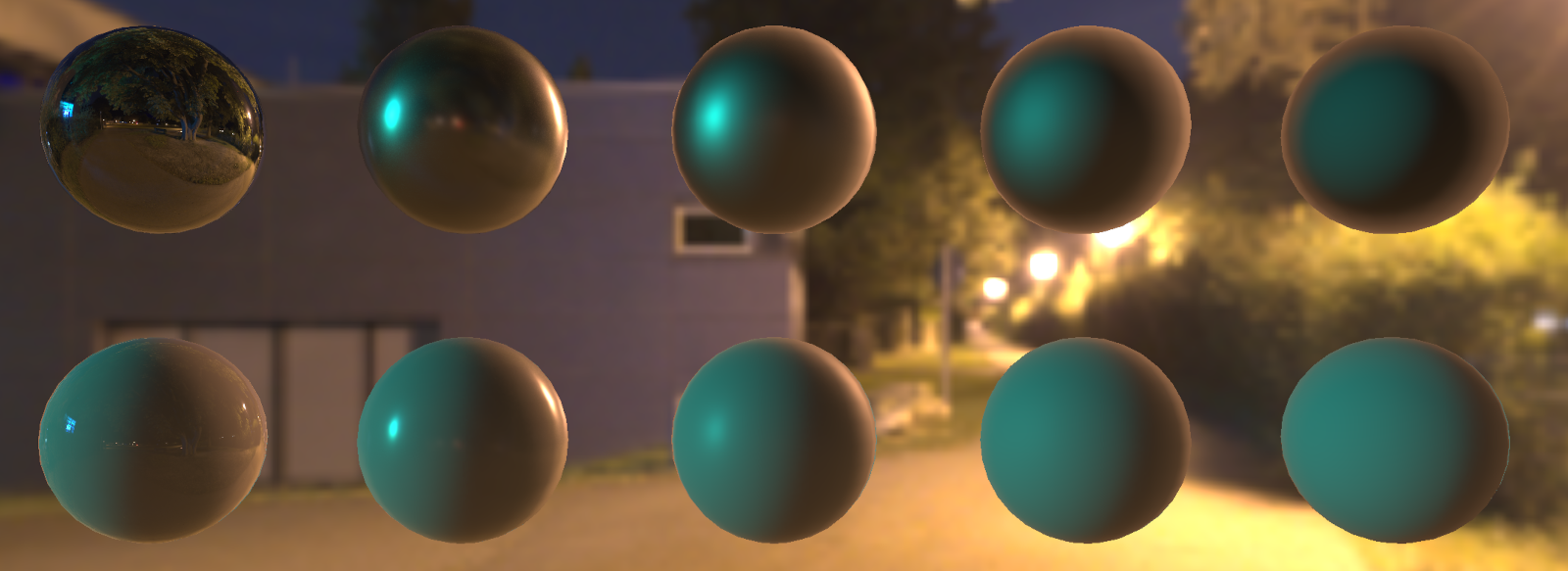
3D.Compute.Scene.ImageBasedLighting
This node adds image-based lighting (IBL) to the scene. Currently, only spherical environment maps are supported.
The image input must be connected to an image data node that contains the environment image.
The color space input selects the color space of the input image. You can choose between "sRGB" and "linear". sRGB is the standard color space used for images in the GSN Composer. However, the sRGB values are always converted to linear RGB before being applied in the shader. Therefore, it may save memory and avoid a conversion operation if an image with linear RGB values is provided directly. In this case, the color space must be set to "linear".
The resolution input selects the resolution of the generated pre-filtered environment maps that are used during rendering. A higher resolution requires more memory.
The samples input selects the number of samples for generating the pre-filtered environment maps. Use more samples for less noise.
The MipmapOffset input defines the mipmap level for sampling from the input image (as an offset from the default). Use positive numbers for less noise, negative numbers for higher accuracy.
The radiance factor input sets a multiplicative factor for the radiance that is read from the environment image. Use a factor larger than 1.0 for more brightness and a factor below 1.0 for less brightness.
The display input toggles whether to display the input image in the background, and the hide input hides and disables the light.
In the example below, we see two rows of spheres. The material in the top row has a metallic parameter of 1.0. The bottom row has a metallic parameter of 0.0, which corresponds to a non-metallic (dielectric) material. The roughness of the sphere's material is increased from 0.0 to 1.0 from left to right. The scene is lit by the environment image that is shown in the background.
3D.Compute.Scene.Texture
The Texture node allows setting a texture for all of its child meshes in the scene.
The image input must be connected to an image data node that contains the texture image.
The target input selects which material property is changed by the texture. The choices are:
- BaseColor: The RGB channels of the input image affect the base color of the material
- Roughness: The green channel of the input image affects the roughness of the material
- Metallic: The blue channel of the input image affects the metallic parameter of the material
- Normal: The RGB channels of the input image define the offset of the surface normal in tangent space
- Emission: The RGB channels of the input image affect the emission of the material
The mesh group input selects to which mesh group the material is applied ("-1" = all mesh groups). If another Texture node with the same mesh group and target is added to the scene further down the scene tree (closer to the child mesh), it overwrites the settings of the Texture node higher up the tree. If the mesh group is set to "-1", the texture settings for all Texture nodes with the same target higher up the tree are overwritten.
The color space input selects the color space of the input image. You can choose between "sRGB" and "linear". sRGB is the standard color space used for images in the GSN Composer. However, the sRGB values are always converted to linear RGB before being applied in the shader. Therefore, it may save memory and avoid a conversion operation if an image with linear RGB values is provided directly. In this case, the color space must be set to "linear".
Selecting the wrong color space is a very common mistake when applying textures. Typically, textures for roughness, metallic, and the normal map are stored in linear space by the exporting application because they contain data that is not meant to be directly viewed as a color on a display. In contrast, the textures for base color and emission are typically stored in sRGB. This convention is followed, for example, by the glTF 3D file format.
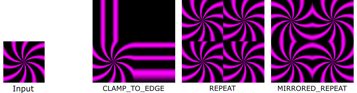
The wrapS and wrapT inputs select the wrap mode of the texture in $s$ and $t$ directions, respectively. The wrap mode controls how a texture is applied to a mesh surface for which the texture coordinates are outside the standard range of [0.0, 1.0].
The combine input selects how the texture data is combined with the material properties for the same target. The options are:
- Replace: Only the texture data is used. The material setting of the same property is not considered.
- Modulate: The texture data and material settings are multiplied
- Add: The texture data and material settings are added
- Subtract: The texture data is subtracted from the material settings
Setting the bypass input to "true" bypasses the effect of the Texture node.
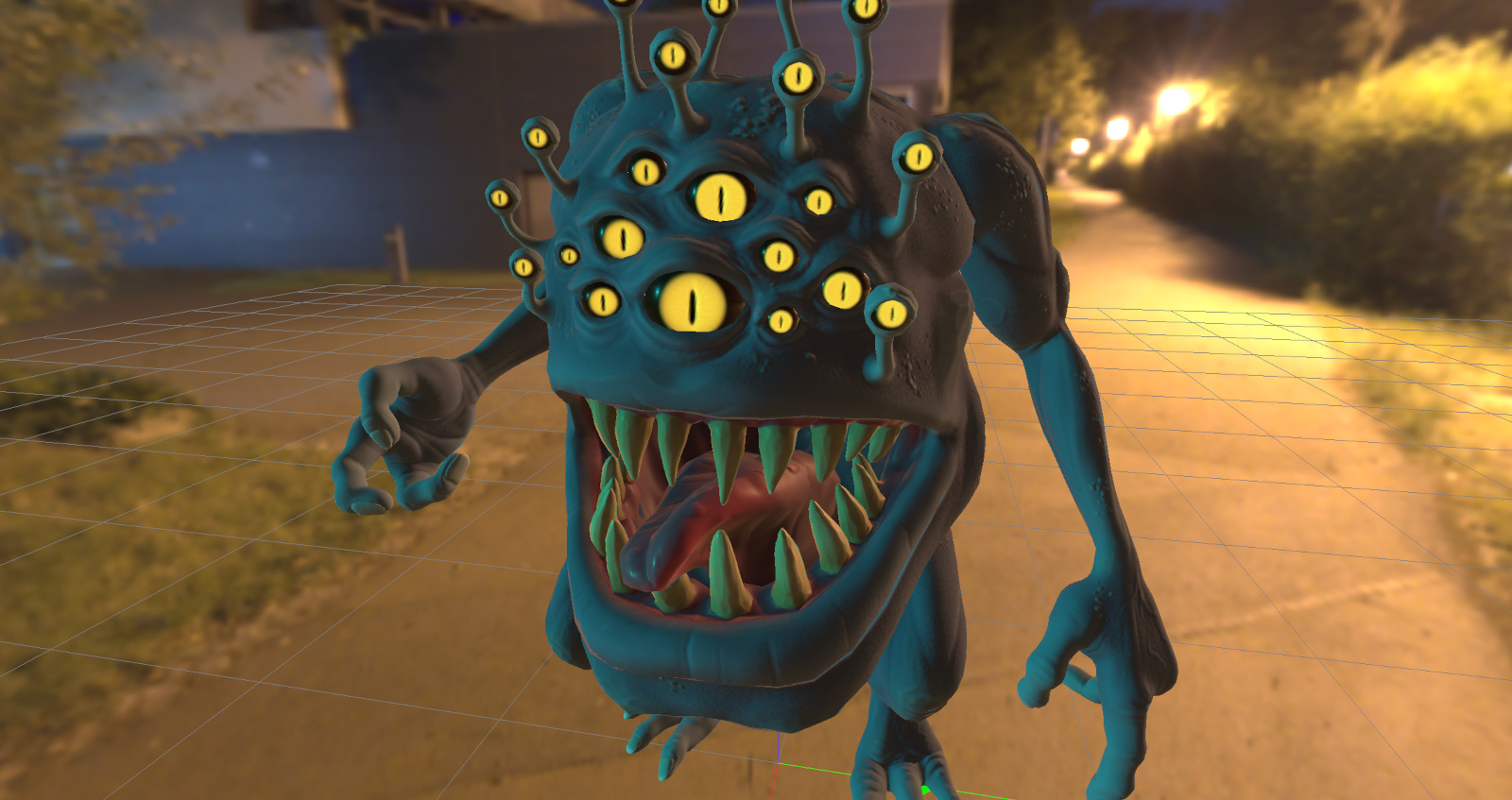
In the example below, four 2D textures are added to the 3D mesh of a stone demon. The textures for base color and emission are given in the sRGB color space. The textures for roughness and the normal map are in linear space.
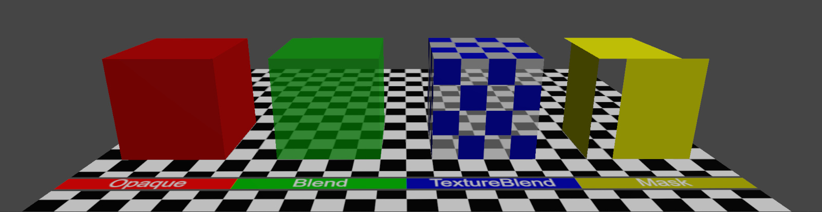
3D.Compute.Scene.Transparency
This node sets the transparency of a material for all of its child meshes in the scene.
The mode input selects the transparency mode. The options are:
- Opaque: The surface is fully opaque (non-transparent).
- Blend: The shaded surface material is blended with the background. The blending factor is given by the alpha input. A value of 0.0 means fully transparent, a value of 1.0 means fully opaque.
- TextureBlend: Same as the "Blend" option, but the value for blending is read from the alpha channel of the BaseColor texture.
- Mask: A value is read from the alpha channel of the BaseColor texture. If the texture value is smaller than the cutoff input, the surface is fully transparent, and otherwise fully opaque.
The culling input enables back- or front-face culling of surface polygons. The options are:
- Disabled: No back- or front-face culling is performed. The polygons can be viewed from both sides.
- Back-Face: Enable culling of polygons that are facing away from the camera.
- Front-face: Enable culling of polygons that are facing toward the camera.
The mesh group input selects to which mesh group the transparency settings are applied ("-1" = all mesh groups).
In the example below, all four options for the mode input are demonstrated.
3D.Data.Scene
A scene data node contains a description of how a 3D scene is composed. It can be used as input for a Rasterizer or Ray Tracer to generate a rendering of the scene.
A scene consists of a hierarchical scene tree. This tree contains scene elements (e.g., cameras, lights, and transformations) and their parameters. These parameters may include references to 3D meshes and images. For example, the MeshInstance node references a 3D mesh, and the Texture node references an image. This means that the same mesh or image can be used multiple times within a scene. Only the reference is stored in the scene, not the mesh or image data itself. Reusing resources like this can save a lot of memory because the mesh or image data is stored only once.3D.Compute.Scene.Merge
This node merges two scenes. An output scene is generated in which the two input scenes are the children. Therefore, the merge node is essential in building a hierarchical scene tree.
3D.Compute.Scene.Similarity
This node applies a 3D transformation (translation, rotation, and uniform scaling) to all its children in the scene tree hierarchy.
In the following example, a toy digger is created from several mesh instances that are arranged in a hierarchical scene tree using the merge node. The similarity node applies a 3D transformation to all the children. E.g., if the "Turret" is rotated, all the children ("MainArm", "Boom", and "Shovel") are rotated in the same way.
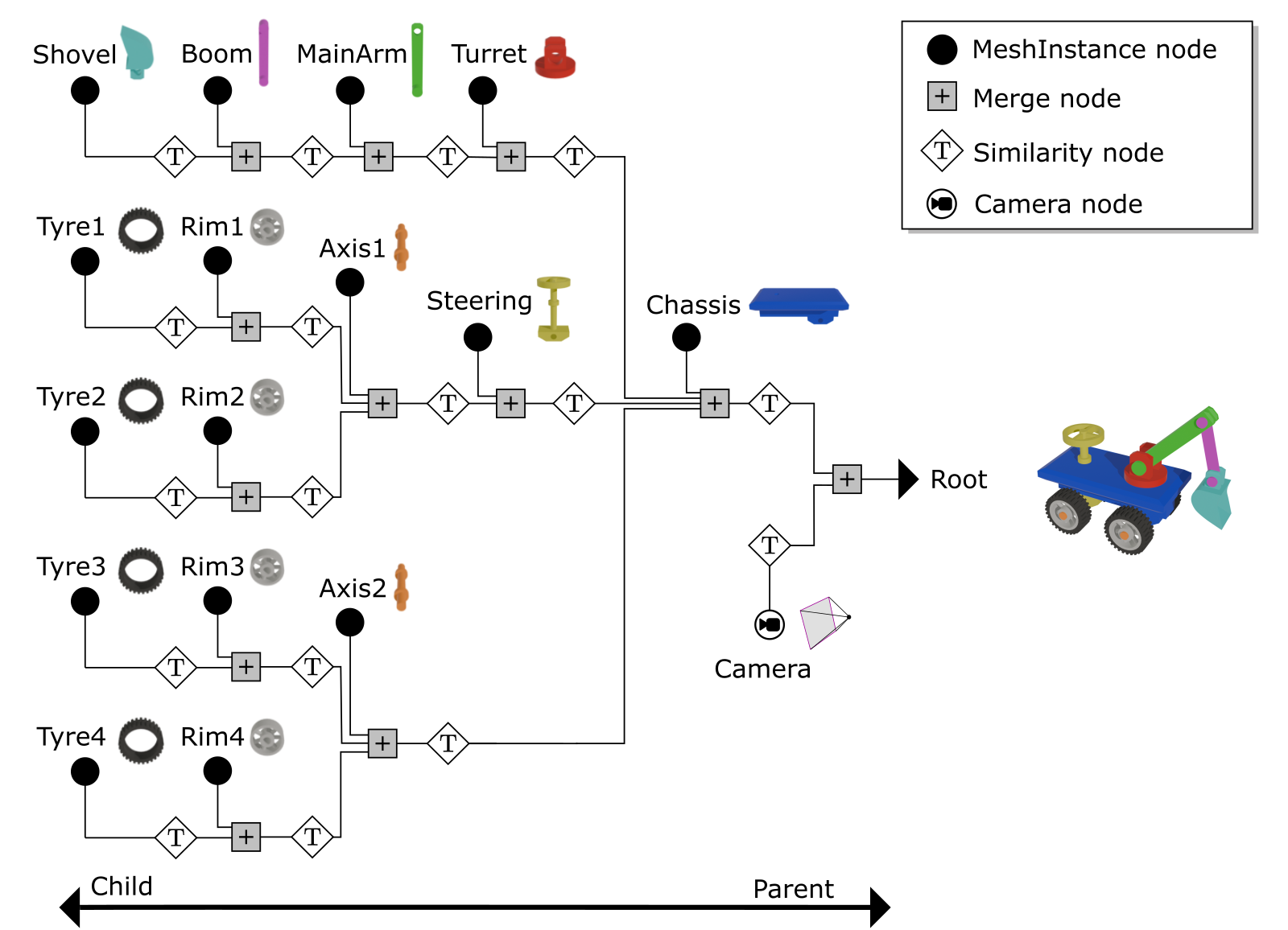
In the GSN Composer, child-parent relations are created from left to right. This is because the merge node takes children from the left and generates a parent on its right side. Consequently, the root of the scene tree is on the far right. The root of the scene tree is typically connected to a Rasterizer or Ray Tracer for rendering.
The similarity node applies a 3D transformation. The translation can be set using the translationX, translationY, and translationZ input slots. The rotation can be defined via the rotationX, rotationY, and rotationZ input slots. A uniform scaling value can be set with the scale input.
The RotOrder input selects the order in which the rotation is applied. For example, for the setting "Rx Ry Rz", the rotation sequence is first around the z-axis, then around the y-axis, and finally around the x-axis.
The order selects the order in which the transformations are applied. For example, for the setting "T R S", transformations are first scaling, then rotation, and finally translation.
3D.Compute.File.LoadScene
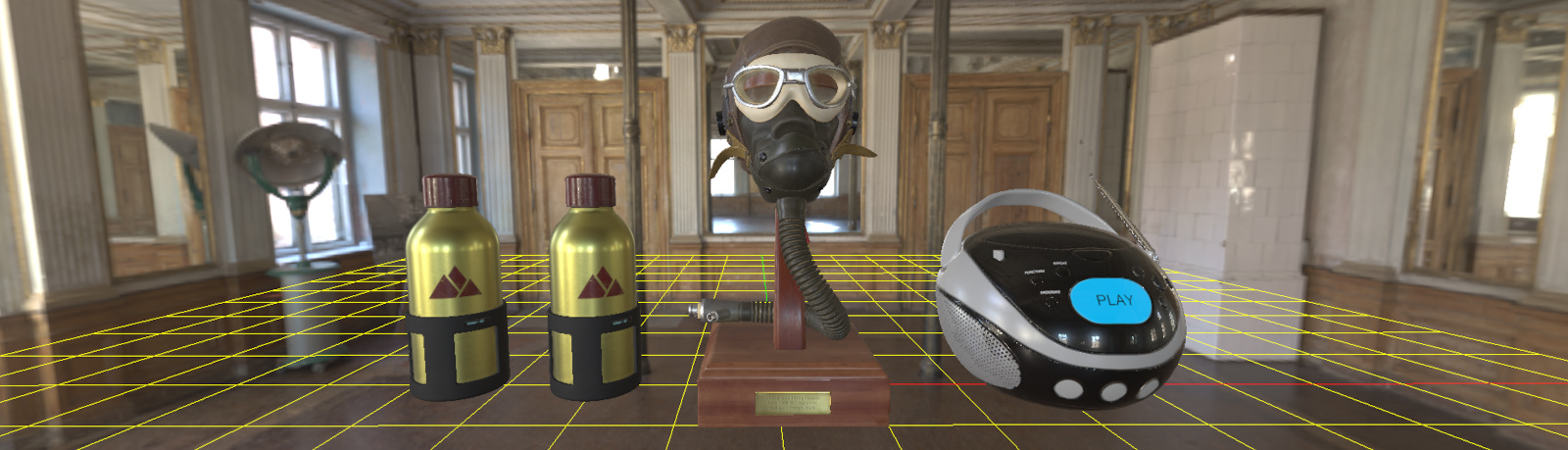
This node loads a 3D scene from a glTF file. Currently, only the binary glTF format with the file extension ".glb" is supported.
In the example above, three different GLB files are loaded: WaterBottle, FlightHelmet, and BoomBox.
The output of the LoadScene node is a scene data node, which contains a description of the 3D scene. Additional outputs are a vector of 3D meshes and a vector of images. References to these meshes and images are used in the 3D scene description. In the example above, the "FlightHelmet" glTF model is composed of 12 different meshes, in addition to 15 different images that are used as textures.
A GLB file can be uploaded into the project via the Upload Resource dialog. This dialog is accessible via the Project dialog in the GSN Composer. It is also possible to drag & drop files directly into the graph area. A resource name is created during the upload. The same resource name must be specified in the filename input slot of the LoadScene node in order to load the corresponding file.
There are several Boolean input slots to include or exclude certain data from the input file:
- Materials: selects whether to apply materials to the meshes.
- Transforms: selects whether to apply 3D transformations to the meshes
- Cameras: selects whether to add cameras to the scene
- Lights: selects whether to add lights to the scene
The Boolean input normalize selects whether to normalize the output size of the entire scene to the maximum range of [-1, 1] in all three dimensions.
The recenter input selects how the mesh should be re-centered. The "none" option disables any transformation. The "bounding box" option applies a transformation to the loaded scene such that the scene's transform center (pivot point) is at the center of its bounding box. The "Min. X" option performs the same centering, but for the x-dimension, the scene's transform center is set to the minimal vertex x-value that is found in all meshes. As the glTF format defines the positive y-axis as the default up-direction, the "Min. Y" option is often useful for placing models upright on the ground.
Unlike the glTF convention, which defines the positive y-axis as the default up-direction, the positive z-axis is the default up-direction in the GSN Composer. Consequently, imported glTF models often require an additional rotation by 90 degrees around the x-axis to appear in the intended orientation. This rotation can be performed by adding a similarity transformation node after the LoadScene node, as shown in the example above.
The disable input disables the loading of the file, resulting in an empty scene as the output.
3D.Compute.Render.Raytracer
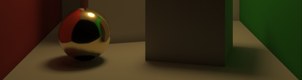
The raytracer node renders a 3D scene using a ray tracing approach. This is slower than rasterization but more realistic. Ray tracing generates (soft) shadows, multiple-bounce reflections, and accurate indirect lighting, as can be seen in the above example.
An essential input of the raytracer node is the InputScene slot, which expects a scene data node. A scene data node contains a description of how the scene is composed. It consists of a hierarchical scene tree that contains parameters of scene elements (cameras, lights, etc.)
Given the scene input, the raytracer node generates a rendering of the scene using the first active camera that is found in the scene tree. If no active camera is found, a default camera is used.
The canvas width and canvas height inputs define the size of the output image.
A scene may contain multiple layers that are separately rendered on top of each other. The layer input selects the scene layer that is rendered. If the layer is set to "-1", all available layers are rendered.
The background input selects the color of the background that the canvas is filled with before any layer is rendered.
The tone mapping input selects the tone mapping approach that is applied before an outgoing radiance $L_o$ is written to the output image:
- sRGB (default): transforms the outgoing radiance $L_o$ to sRGB, which is the standard color space used for images in the GSN Composer
- Filmic: uses the Filmic tone mapping operator
- Linear: no color transformation is applied to the outgoing radiance $L_o$
- Raw: same as "linear", but all other settings clamp the output values to the range [0.0, 1.0], which is not done here
The wireframe input activates an overlay of a wireframe rendering for the meshes. The wireframe's color can be selected with the wire color input.
The glyphs input activates the rendering of glyphs for otherwise non-visible scene elements, such as lights, cameras, or helpers.
The sampling input sets the number of primary ray samples per pixel. Using more samples increases the computation time but generates an output image with less noise.
The final output image is composed of multiple image patches via temporal accumulation. The currently rendered patch is provided at the patch output slot. The patch width and patch height inputs define the size of the patch image. Once a patch is rendered, its contribution is added to the final output. Internally, the raytracer node uses WebGL GLSL shaders to speed up the computation. However, if a GLSL shader takes too long to render a patch, the website may crash or become unresponsive. Therefore, it is important to choose a sufficiently small patch size so that updates occur frequently (several times per second). The time it takes to render a patch depends on your GPU and the complexity of the scene. If you have a powerful GPU, you can carefully increase the patch size. The rendering is fastest when the patch size is equal to the size of the output image because fewer updates need to be visualized.
The light bounces input sets the maximum number of indirect light bounces. A higher number might increase the computation time for each primary ray sample.
When ray tracing a scene, it may happen that the shadow ray towards a light source does not hit a real occluder but the geometry it originates from. This can cause erroneous self-shadowing (shadow acne). To prevent erroneous self-shadowing, a slope-scaled shadow bias is used. The shadow ray's origin is moved away from the hit position on the surface using a small offset in the direction of the surface normal. This shadow bias is not constant but depends on the dot product of the light direction $\mathbf{l}$ and the surface normal surface normal $\mathbf{n}$ as follows:
When randomly sampling the indirect light direction in a scene, it may occur that some indirect light directions contribute a very high radiance value. This is not necessarily problematic, but in some scenes, very bright pixels (so-called "fireflies") may occur. Fireflies are a form of high-frequency noise that averages out when more samples are used. However, if a firefly is a result of a low-probability event, a huge amount of samples may be needed. The clamp indirect input defines the maximum radiance for an indirect light contribution. Radiance values above this threshold are clamped. Consequently, this parameter can be used to prevent fireflies. However, this comes at the cost that the renderer output is biased towards an overall darker result because some light is lost. The clamping is disabled when the clamp indirect input is set to a value smaller than 0. In general, clamping of radiance values is only applied to indirect light. Direct light from light sources is not affected.